Aug 2018
Our new home is being built and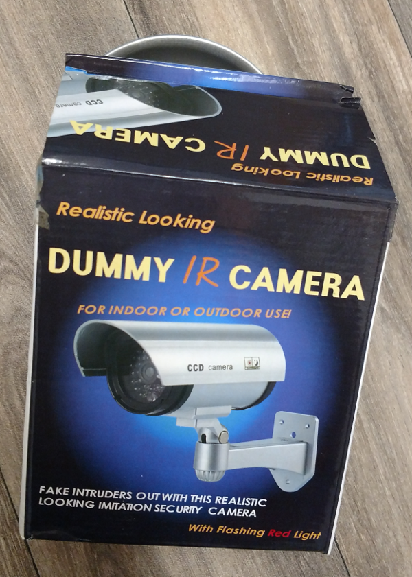 I wanted to create a time lapse video of the construction.
It’s outside and required an outside enclosure. So we ordered a dummy bullet camera case to hold the Raspberry Pi computer.
24 hour video with a night time IR flood light requires an IR shutter for proper daytime color.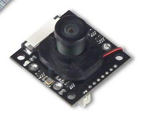 Solved with a Raspicam compatable camera with a “motorized” IR-Cut. Not sure if motorized is a good translation but it means the IR-Cut filter can be switched in and out via software.
Unboxing the dummy bullet camera case presented some pleasant surprises.
In the rear cover is a dummy connector housing with a fake cord. remove the fake cord and the opening has the same shape and is just a tiny bit larger than a female USB A connector. 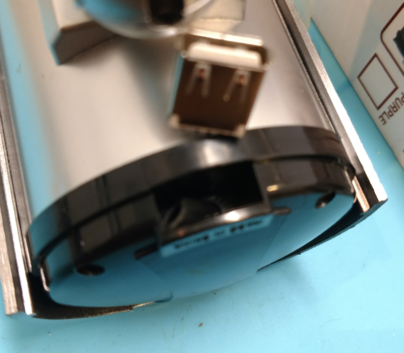 This was perfect as the camera needs 5VDC power and a hard disk attached and the case is too narrow to fit a micro USB and the female USB A will supply 5VDC to the RPi It will also feed USB signals to the RPi.
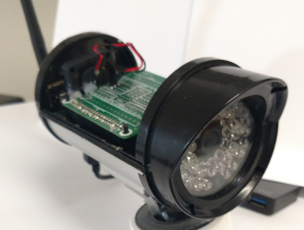
The center piece bottom has small vertical braces on the sides that are conveniently the same width apart as a Raspberry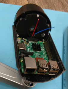 Pi 3 B+ and one can rest nicely on the curved bottom. The back of the case neatly covers the ethernet and USB ports maintaining water resistance.
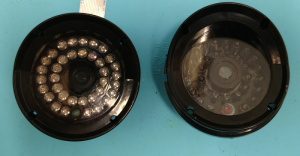
 The front of the case has a dummy IR array that is replaced by a 36 LED IR illuminator . Replacing the existing fake LEDs is accomplished by cutting the fake LEDs off of the front mounting plate. The standard 36 LED array is just a bit larger than the housing and needs to be trimmed slightly to fit inside the front housing.
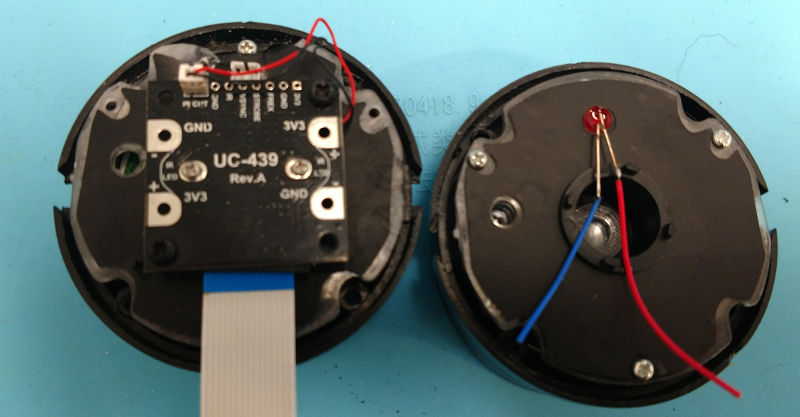
The Arducam camera module fits conveniently on the inside of the front mounting plate and the attached lens and shutter place the lens at exactly the place the dummy lens sat.
The IR LED array replacing the dummy requires 12VDC and a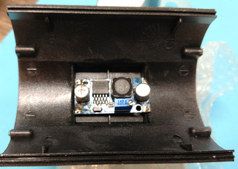 boost converter fits well at the bottom of the case where the camera mount is located.
The USB size opening on the back was almost completely sealed but it was simple to cut the back of the connector opening. 
 The USB A female connector was attached to some .1 in center perforated proto-board and a header added to mate to a connector on another small proto-board that the boost converter was mounted on. A couple of wraps of vinyl electrical tape made the USB connector fit tightly in the connector opening however there was a 4mm gap on the narrow side so 2ea 2mm plastic spacers were added to shim out the USB to completely fill the opening .
To make the camera easily maintainable some clear acrylic sheet cut to the exact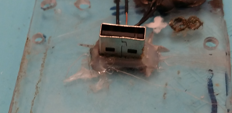 size of the Raspberry Pi was used. On the boost board another USB female vertical mount connector was added. It was just the right height to fit under the acrylic sheet.An opening was cut in the acrylic sheet to fit a matching male connector. A roto tool was used to cut a male A USB connector so when it is mated to the female USB, it is flush with the Rpi side of the board.
[EDIT] I may eliminated the USB to USB on the acrylic sheet and moved the connection to the back USBs with a cut male A USB connector mating to the standard USB input on a zero clearance board (see next blog).
With a lot of care, the male USB can be cut with a roto tool such that the leads from the connector are not cut off but folded over and connected to wires.
The Pi generates heat and a fan is needed to cool it. The fan is a MakerFocus 2pcs Raspberry Pi DC Brushless Cooling Fan. The 5VDC from the USB needs to be connected to the Pi. 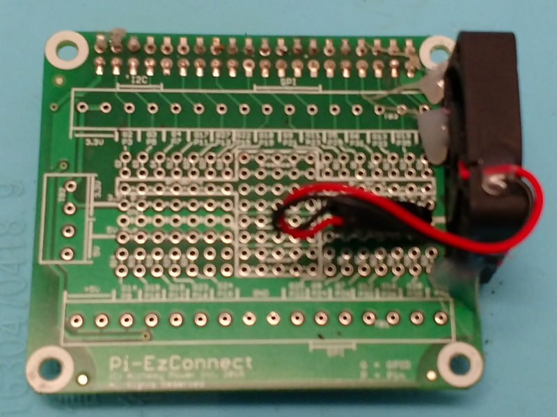 However the case has a battery compartment that limits the height allowed on a HAT board. A perfect solution was to use an unpopulated Pi-EzConnect board. The rear side of the board is mostly ground and can be trimmed to fit the fan and still have room for stepper motor drivers for when the camera becomes a streaming security cam.
The Pi-EzConnect board has another big advantage because it has a fuse in the 5VDC line. 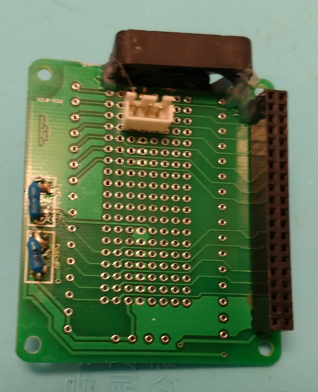 The power from the USB is fed to the board’s 5VDC line which bypasses the Raspberry Pi’s fuse. Now with the Pi-EzConnect board the Pi is fused. Note that due to the height restriction due to the battery compartment, the connector for 5VDC is on the bottom of the board. It just clears the components on the Pi.
As this project is wrapped up, the USB will connect to a hard disk in a separate housing. Another blog will complete the assembly and show the code for 12 hour recordings with 1 second frames.