The Coop CPU (Computer) and connections
One of the incentives for computerizing the coop
was a chance to use the new single board computers.
I had worked with single board computers in the late 1980s
but the new ones have so much more in the way of I/O and control.
Here is the main computer board and add ons I used in controlling the coop.
This one was one of the first Raspberry Pi computers.
The Computer board is a Raspberry Pi model 3
Not all of the GPIO pins are available for PIR sensor input but three work fine.
I did not buffer the GPIO pins connected to the PIR sensors.
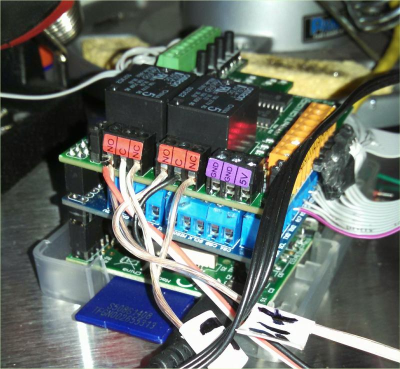
The GPIO pins are used and are made accessible by the the buffered I/O board
My main reason for making the the buffered I/O was to make the protect the GPIO pins from voltage spikes or shorts.
![]()
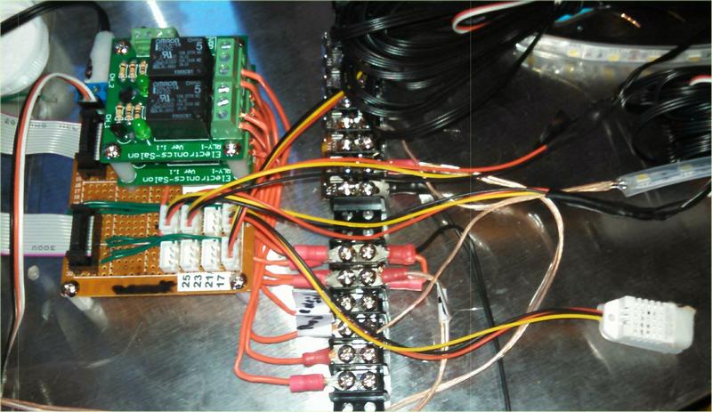
The ribbon cables from the buffered I/O connect to a distribution board which has three relays.
The three wire connectors supply 5VDC ground and the the buffered I/O input for that PIR. There is also a direct connection to the I2C
for modules like the temperature and humidity sensor (lower right).
This brings up a caveat in design. When purchasing add on relay boards, check the activation voltages.
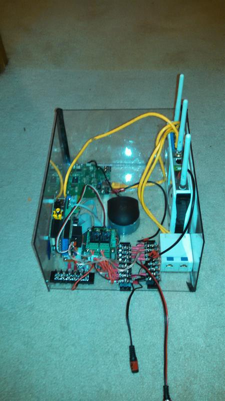
The fully assembled coop cpu is installed in a weather proof enclosure on the side of the coop.
In this image you can see the Camera board for the internal view of the coop,
the router and connections for additional devices and cameras
On further pages I will describe the light modules and the code to operate the coop.
written by Doug Wyman